news | Feature Lines |
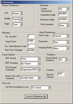
| Improved Feature Line Treatment in Harpoon Recent releases of Harpoon have included some important improvements to the codes handling of feature lines, which are referred to as FLs in the following article. Feature lines are used in Harpoon to capture and retain the important geometric features of a model. These include areas of high curvature and the boundaries (free edges) of model parts. Harpoon will always attempt to retain these features during meshing. Target mesh sizes can be defined on different Fls, or mesh sizes can be specified on the polygons.
Harpoon defines two types of FLs:
For models that consist of more than one part, a separate FL part is created for each model part. FLs may be merged, renamed, deleted or separated using the same methods as for polygons -- namely by Region or by Feature. A region is defined as all line segments connected to one that the user selects. This is done by double-clicking on a line segment with the left mouse button (the number of the segment will appear in the background window). Applying the option Surface > Separate > Line Segment by Region on the selected segment results in the original line part being split into two parts -- one for all line segments connected to the segment selected, and the other being all segments not connected to it. Alternatively, applying the option Surface > Separate > Line Segment by Feature on the FL results in multiple new line parts according to the Separation Angle in Harpoons preferences.
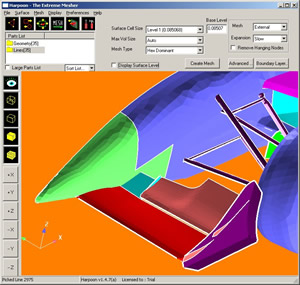
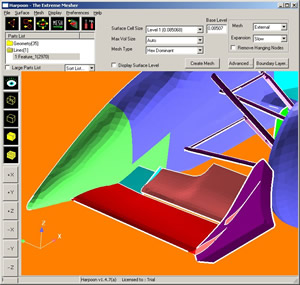
It is important to distinguish between the two angle preferences. Separation Angle is used to separate polygons and line segments based on the included angles between adjacent polygons or line segments. Feature Angle is used to create FL parts as described above. By default, Harpoon creates an FL part for each model part to which it is associated. If a single FL part is desired, the command line option -nolineperpart can be used when starting Harpoon. FLs on the free edges of model parts may, or may not, be desired. It is possible to suppress the creation of FLs on the free edges of a model part by starting Harpoon with the command line option -noedgeline. This option will also invoke the -nolineperpart option. FLs will only be created on part edges if the angles relative to the adjacent model part exceeds the extraction angle in the preferences. Figures 3a and 3b show a model with and without FLs on part edges.
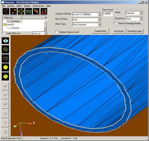
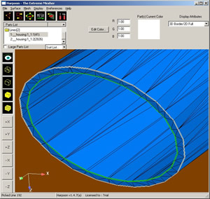
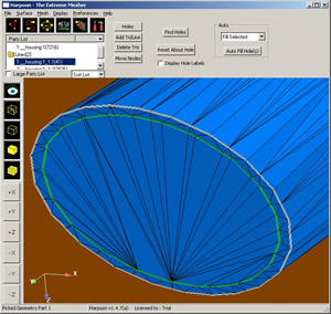
FLs serve one other important use in Harpoon. If FLs describe closed circuits, for example around an opening in a model, they can be used to close the holes. This is especially useful when Harpoons hole finding feature - which in reality looks only for free edges (sides of polygons shared by only one polygon) - results in no holes being found, although they appear in the model. These are typically not free edges, but openings in thick-walled parts. Since the edges of these openings are usually sharp, they will appear as FLs. Separating those describing an opening using the Surface > Separate > Line Segment by Region procedure described above results in a single line part. The user then selects this line and closes the hole using the normal hole-closing feature. Figures 4a-c show the sequence of steps to define and close an opening in a thick-walled part.
The information above may be found in Harpoons User Guide, viewed through Harpoons Help facility.
|
|